
- June 11, 2015
- Posted by: Surender Kumar
- Category: Cisco Routers
Cisco Router Basics Components
Table of Contents
The basic components of Cisco Router and Switch are approximately same. So I will not discuss this in Switch section. Main components of Router/switch are:
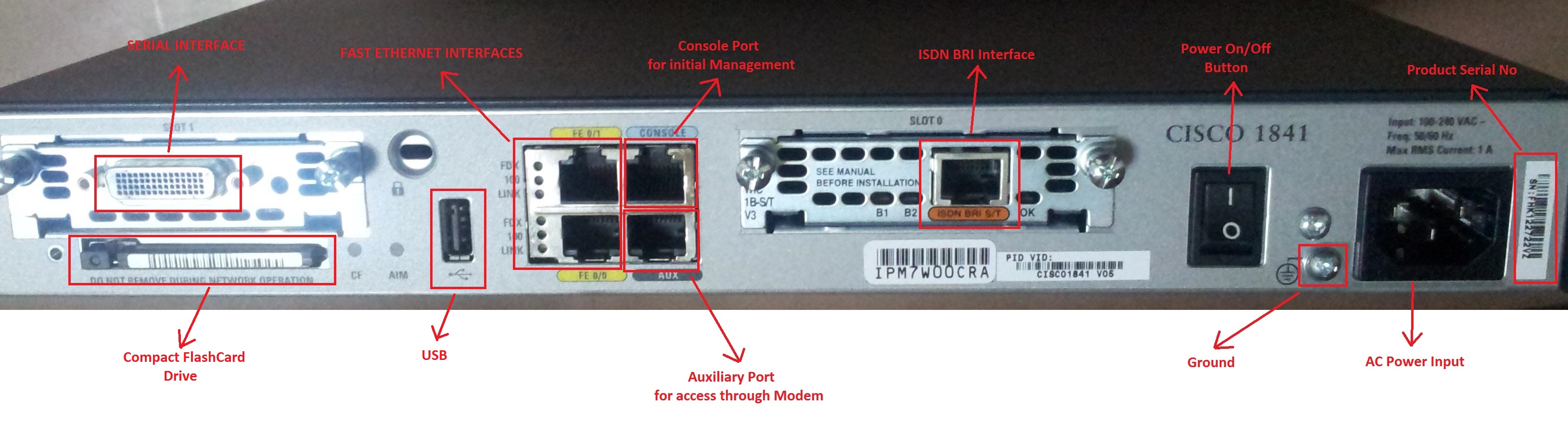
Interfaces
Interfaces (also known as ports) allow us to connect the router to other devices. Router has different types of interfaces like Serial, Ethernet, Console, AUX etc. This is beyond the scope of this guide to cover each and everything in details but I will try to cover all in brief.
- Serial interface is used by ISP to provide WAN connections as a frame relay, T1, T3, etc. The port used is RS232. Ethernet (FastEthernet or GigabitEthernet) interface is used in LAN and WAN connections (RJ45).
- Console Port is used for Management of router, we can directly access the router IOS using console port even if router is not configured yet (initial configuration).
- Auxiliary (AUX) port is used for accessing the router (remotely) via Modem. It is configured to dial in to the router for troubleshooting purposes when regular connectivity fails.
- Basic Rate Interface (BRI) is intended for the home and small enterprise. BRI include a number of B-channels and a D-channel. Each B-channel carries data, voice, and other services. The D-channel carries control and signaling information. BRI consists of two 64 Kbps B-channels and one 16 Kbps D-channel. Thus, a Basic Rate Interface user can have up to 128 Kbps service.
Other Components
- CPU: Like in computers, CPU is main chip which performs all the processing like routing decision, NAT, access list etc. In day to day operations, the CPU utilization on a normal router wouldn’t exceed 20-30%. If your router’s CPU usage is beyond this limit, you need to check for the cause.
- IOS: Internetwork Operating System (IOS) is the operating system of Cisco routers and switches which is loaded into the main memory during startup. The size of IOS image can range from 5MB to 50MB depending upon the type of router/switch. Cisco keeps updating the IOS software release to provide bug fixes and additional features to users. Latest software release from Cisco is 15.x.
- Bootlaoder: Also known as bootstrap image, is a subset or striped down version of the Cisco IOS that is used to download main Cisco IOS software image to the router in recovery situations.
- RAM: Random Access Memory (RAM), sometimes known as DRAM is where the router loads the IOS and running configuration file when it is up and running. It works exactly the same way as computer’s main memory, where the operating system and other programs are loaded. The amount of RAM your router needs depends on the size of the IOS image, configuration file, routing table size. Generally, routers/switches have memory ranging from 32 to 64 MB but it can vary according to your router model. High end routers can have higher capacity memory.
- NVRAM: Non Volatile RAM (NVRAM) holds the router’s startup configuration file. Unlike RAM, the contents of NVRAM are not lost when the router is powered down or reloaded. The size of NVRAM is very small (8KB to 128KB) as compared to that of RAM because it only stores startup configuration file which is generally very small in size.
- ROM: The Read Only Memory (ROM) contains some code, like the bootstrap and POST, which helps the router to do basic tests like Power On Self Test when it’s powered on or reloaded.
- Flash memory: Generally referred to simply as ‘flash’, stores the IOS image. Flash is nothing but erasable programmable ROM (EEPROM). Flash memory contents are not lost on reload and it can be altered by user when upgrading the IOS version on router/switch. The size of flash can range from 16 MB to 64 MB generally but it can be bigger in high end routers/switches. It fits into a special slot normally located at the back of the device.
- Configuration Register: The configuration register can be used to change router behavior like to boot the IOS image from its flash, TFTP server or just load the rx image. The configuration register can be set from configuration mode using the config-register command and from ROMmon mode, using the confreg command. By default configuration register setting is 0x2102 which indicates that the router should attempt to load a Cisco IOS Software image from Flash memory and load the startup configuration with a console speed of 9600 baud.
Getting Started with Router Configuration
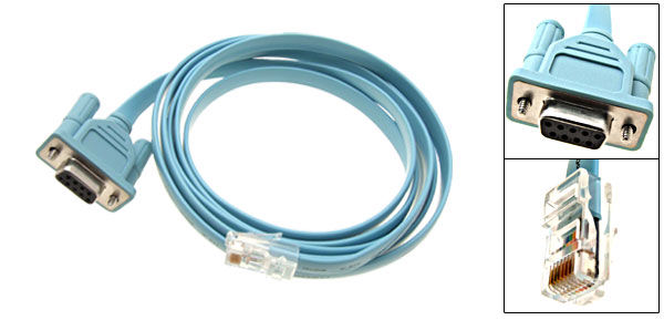
First of all, we need to connect the router to power source and connect the router to PC using Console cable. Console cable is cable having RJ45 connector at one end and DB9 female connector at other end. In order to connect your router/switch to computer, you have to look for a serial port (DB9 Male) on the back of your PC. Console cable looks like as shown below:
Connect the Router/switch to computer as shown in image below:
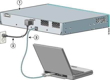
After connecting, power on the router/switch. Look at the back panel of device, switch on the power button if it has one. Mostly Routers are given with power button but switches are not.
Connecting to Router
You need a software in order to access the IOS on your PC. If you are using Windows XP, there is a built in tool called hyperterminal. If you are running Winodws 7 or higher, you need to download a small tool named Putty from here. Putty will also work in Windows XP as well.
Hyperterminal configuration:
Click Start | Programs | Accessories | Communications | HyperTerminal or just type hypertrm command in Run.
- Once HyperTerminal opens, it will automatically prompt you to create a new connection if none exist. If no connection(s) exists, you can click File | New Connection to create a new one.
- Specify a name for the connection, choose an icon, and click OK.
- In the Connect To dialog box, choose the COM port being used by your modem (usually COM1 or COM2) from the Connect Using drop-down list and click OK.
- In the port property sheet that appears, enter the following values:
- Bits per Second: 9600 (or desired baud rate)
- Data Bits: 8
- Parity: None
- Stop Bits: 1
- Flow Control: none
- Click OK
- Click OK to start connection to your router/switch.
Putty configuration:
- Download and run the file Putty.exe.
-
Expand Connection > Serial. Enter the port number inside “Serial line to connect to” text box. The port number is COM4 in below example. The port number may be different in your computer. Enter the correct port number when you connect from your computer. Enter other values also as shown below.
- Bits per sec: 9600
- Data bits: 8
- Parity: none
- Stop bits: 1
- Flow control: none
- Click Session and click “Serial” radio button. Verify whether you can see the port number and the baud rate (9600) you had selected before. Click “Open” to connect to Cisco Router or Switch IOS.
Once connected to your router/switch, you can start configuring your device.