
- July 17, 2015
- Posted by: Surender Kumar
- Category: Cisco Routers
Policy Based Routing (PBR)
Table of Contents
Policy Based Routing is when you want to route the traffic based on a predefined policy rather than the normal routing mechanism used by layer-3 devices like routers or layer-3 switches. Typically, the traffic is routed based on the destination but Policy Based Routing gives you more control over routing by extending the existing mechanisms provided by routing protocols. PBR allows you to set the IP precedence and to specify a path for certain traffic, such as priority traffic over a high-speed link.
I will use pretty basic example of PBR so that you can understand how it works.
Consider that you have 2 different networks in your office. One is for Sales department and another one is for Accounts. You have 2 Internet connections from different ISPs as shown below.
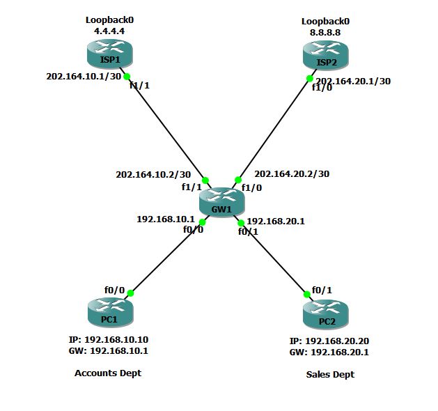
GW1 router in your office is connected to 2 different ISPs: ISP1 and ISP2. You want that Accounts department should use ISP1 and Sales department should use ISP2 to get to Internet.
We will configure PBR on GW1 Router so that the traffic sourced from 192.168.10.0/24 network will be forwarded to 202.164.10.1 (ISP1) and similarly the traffic sourced from 192.168.20.0/24 network will be forwarded to 202.164.20.1 (ISP2).
First of all I will configure PC1 and PC2. I would like to mention that PC1 and PC2 are actually routers but I have disabled IP Routing on these and configured them to use default gateway so that these routers will behave as end hosts (PCs).
Router#conf t
Enter configuration commands, one per line.  End with CNTL/Z.
Router(config)#hostname PC1
PC1(config)#int fa0/0
PC1(config-if)#ip address 192.168.10.10 255.255.255.0
PC1(config-if)#no shut
PC1(config-if)#exit
PC1(config)#ip default-gateway 192.168.10.1
PC1(config)#no ip routing
PC1(config)#end
PC1#
Router#conf t
Enter configuration commands, one per line.  End with CNTL/Z.
Router(config)#hostname PC2
PC2(config)#int fa0/1
PC2(config-if)#ip add 192.168.20.20 255.255.255.0
PC2(config-if)#no shut
PC2(config)#ip default-gateway 192.168.20.1
PC2(config)#no ip routing
PC2(config)#end
PC2#
Now, I will configure ISP1 and ISP2 Routers. To simulate internet connection, I’ve created loopback interface with IP address 4.4.4.4 and 8.8.8.8 on router ISP1 and ISP2 respectively.
ISP1#conf t
Enter configuration commands, one per line.  End with CNTL/Z.
ISP1(config)#int loopback0
ISP1(config-if)#ip add 4.4.4.4 255.255.255.255
ISP1(config-if)#no shut
ISP1(config-if)#int fa1/1
ISP1(config-if)#ip add 202.164.10.1 255.255.255.252
ISP1(config-if)#no shutdown
ISP1(config-if)#exit
ISP1(config)#ip route 0.0.0.0 0.0.0.0 202.164.10.2
ISP1(config)#^Z
ISP1#
ISP2#conf t
Enter configuration commands, one per line.  End with CNTL/Z.
ISP2(config)#int loopback0
ISP2(config-if)#ip add 8.8.8.8 255.255.255.255
ISP2(config-if)#no shut
ISP2(config-if)#int fa1/0
ISP2(config-if)#ip add 202.164.20.1 255.255.255.252
ISP2(config-if)#no shut
ISP2(config-if)#exit
ISP2(config)#ip route 0.0.0.0 0.0.0.0 202.164.20.2
ISP2(config)#^Z
ISP2#
ISP1 and ISP2 routers have been configured with IP addresses and routing, it is time to configure GW1 router. On GW1, firstly I will configure IP addresses according to our sample network.
GW1#conf t
Enter configuration commands, one per line.  End with CNTL/Z.
GW1(config)#int fa0/0
GW1(config-if)#ip address 192.168.10.1 255.255.255.0
GW1(config-if)#no shutdown
GW1(config-if)#int fa0/1
GW1(config-if)#ip address 192.168.20.1 255.255.255.0
GW1(config-if)#no shutdown
GW1(config-if)#
GW1(config-if)#int fa1/0
GW1(config-if)#ip address 202.164.20.2 255.255.255.252
GW1(config-if)#no shutdown
GW1(config-if)#int fa1/1
GW1(config-if)#ip address 202.164.10.2 255.255.255.252
GW1(config-if)#no shutdown
GW1(config-if)#end
GW1#
If you are not yet familiar with Policy Based Routing, then what you will most likely do is to add a default route on GW1 for one (or both) ISP routers but this will not accomplish our goal. This will route the traffic from both networks to same ISP but remember that we want the traffic of 192.168.10.0/24 to be routed through ISP1 and traffic of 192.168.20.0/24 to be router through ISP2.
In real world, you will not have any access to ISP routers. So, you have to configure everything on router which is located at your end. We will configure PBR on GW1 router to accomplish our ultimate goal.
Policy Based Routing Configuration
For PBR configuration, we have to do the following:
- Create an Access Control List to identify the interesting traffic
- Create Route Map
- Create IP Policy.
Let’s create ACL for each network first
GW1#conf t
Enter configuration commands, one per line.  End with CNTL/Z.
GW1(config)#ip access-list extended ACCOUNTS-ACL
GW1(config-ext-nacl)#permit ip 192.168.10.0 0.0.0.255 any
GW1(config-ext-nacl)#exit
GW1(config)#ip access-list extended SALES-ACL
GW1(config-ext-nacl)#permit ip 192.168.20.0 0.0.0.255 any
GW1(config-ext-nacl)#exit
GW1(config)#
I created two ACLs, ACCOUNT-ACL and SALES-ACL to classify the traffic based on source network address and going to any destination.
Keep in mind that we want the complete IP traffic from a particular source network to be routed via specific next-hop. If we were to route only specific type of traffic, we could specify it using extended ACLs because extended access-list gives you more granular control on traffic using source, destination and even port or protocol basis.
Next, we will create Route Map.
Route Maps are similar to access lists; they both have criteria for matching the details of certain packets and an action of permitting or denying those packets but Route Maps also allow you more options for matching a given packet. Route Maps can add to each “match” criterion a “set” criterion which actually changes the packet in a specific manner, or changes the route information in a specific manner.
GW1#conf t
Enter configuration commands, one per line.  End with CNTL/Z.
GW1(config)#route-map USE-ISP1 permit 10
GW1(config-route-map)#match ip address ACCOUNTS-ACL
GW1(config-route-map)#?
Route Map configuration commands:
  continue     Continue on a different entry within the route-map
  default      Set a command to its defaults
  description  Route-map comment
  exit         Exit from route-map configuration mode
  help         Description of the interactive help system
  match        Match values from routing table
  no           Negate a command or set its defaults
  set          Set values in destination routing protocol

GW1(config-route-map)#set ip next-hop 202.164.10.1
GW1(config-route-map)#exit
GW1(config)#
I’ve used route-map command to create the route map with the name USE-ISP1 and permit 10 is a sequence number. Remember that route-map is processed by using sequence numbers starting from lower to higher just like sequence number in ACLs. The route map is just like if/else conditional test used in programming. If any packet matches the criteria, it can take some specific action against that packet. The match ip address ACCOUNTS-ACL command is a test condition for route map means the route-map will test if packets are matching ACCOUNTS-ACL.
You can see the options (lines marked purple) which can be used in route-map. I have used set ip next-hop 202.164.10.1 command because if a packet matches the ACCOUNTS-ACL, it should be forwarded to next-hop address 202.164.10.1.
GW1(config#
GW1(config)#route-map USE-ISP2 permit 10
GW1(config-route-map)#match ip address SALES-ACL
GW1(config-route-map)#set ip next-hop 202.164.20.1
GW1(config-route-map)#exit
GW1(config)#
Similarly, I created a route map USE-ISP2 for SALES network.
We have now created ACLs and Route Maps. Now we have to apply this to an interface. Remember that IP Policy is always applied for ingress traffic. Ingress traffic means the traffic which coming inside. You can apply Route map on interface or VLAN.
Since, Accounts network is connected to GW1 through interface fastEthernet0/0 and Sales network is connected through fastEthernet0/1. So, we will apply route map USE-ISP1 on fa0/0 and USE-ISP2 on fa0/1.
GW1#conf t
Enter configuration commands, one per line.  End with CNTL/Z.
GW1(config)#int fa0/0
GW1(config-if)#ip policy route-map USE-ISP1
GW1(config-if)#int fa0/1
GW1(config-if)#ip policy route-map USE-ISP2
GW1(config-if)#end
GW1#
Route Map is applied using ip policy route-map command.
Policy Based Routing Verification
After applying the Route-Map, it is time to test our configuration. You should know that if PC1 can ping 4.4.4.4 which is behind ISP1 and PC2 can ping 8.8.8.8 which is behind ISP2, this means our PBR is working perfectly fine. Let’s check it out.
PC1#ping 4.4.4.4

Type escape sequence to abort.
Sending 5, 100-byte ICMP Echos to 4.4.4.4, timeout is 2 seconds:
!!!!!
Success rate is 100 percent (5/5), round-trip min/avg/max = 48/67/92 ms
PC1#ping 8.8.8.8

Type escape sequence to abort.
Sending 5, 100-byte ICMP Echos to 8.8.8.8, timeout is 2 seconds:
UUUUU
Success rate is 0 percent (0/5)
PC1#
The above output says PC1 can’t go through ISP2 which is pretty much expected.
PC2#ping 4.4.4.4

Type escape sequence to abort.
Sending 5, 100-byte ICMP Echos to 4.4.4.4, timeout is 2 seconds:
UUUUU
Success rate is 0 percent (0/5)
PC2#ping 8.8.8.8

Type escape sequence to abort.
Sending 5, 100-byte ICMP Echos to 8.8.8.8, timeout is 2 seconds:
!!!!!
Success rate is 100 percent (5/5), round-trip min/avg/max = 64/65/68 ms
PC2#
Same thing happened at PC2 as well. To be more confident, let’s debug Policy Routing on GW1 and check what is happening there.
GW1#debug ip policy
Policy routing debugging is on
GW1#
When I run ping from PC1 to 4.4.4.4 address, the PC1 will get successful Reply the debug will show the following output.
GW1#
*Jul 18 07:44:48.956: IP: s=192.168.10.10 (FastEthernet0/0), d=4.4.4.4, len 100, FIB policy match
*Jul 18 07:44:48.956: IP: s=192.168.10.10 (FastEthernet0/0), d=4.4.4.4, g=202.164.10.1, len 100, FIB policy routed
*Jul 18 07:44:49.088: IP: s=192.168.10.10 (FastEthernet0/0), d=4.4.4.4, len 100, FIB policy match
*Jul 18 07:44:49.088: IP: s=192.168.10.10 (FastEthernet0/0), d=4.4.4.4, g=202.164.10.1, len 100, FIB policy routed

[output cut]
Note the line saying (Forwarding Information Base) FIB policy match. It means a match is occurred on policy and then FIB policy routed means the packet is routed.
This was just a simple example of Policy Based Routing. You can use PBR in any scenario when you want to influence the routing table on the basis on source address because regular routing mechanism and routing protocols can only route on the basis of destination. You can also use PBR with VLANs as well. There are lot of applications of policy based routing and route maps.
Benefits of Policy Based Routing:
- Source-Based Transit Provider Selection — ISPs and other organizations can use policy-based routing to route traffic originating from different sets of users through different Internet connections across the policy routers.
- Quality of Service (QOS) — Organizations can provide QOS to differentiated traffic by setting the precedence or type of service (TOS) values in the IP packet headers at the periphery of the network and leveraging queuing mechanisms to prioritize traffic in the core or backbone of the network.
- Cost Saving — Organizations can achieve cost saving by distributing interactive and batch traffic among low-bandwidth, low-cost permanent paths and high-bandwidth, high-cost, switched paths.
- Load Sharing — In addition to the dynamic load-sharing capabilities offered by regular destination-based routing supported by Cisco IOS, network administrators can now implement policies to distribute traffic among multiple paths based on the traffic characteristics.