
- July 27, 2015
- Posted by: Surender Kumar
- Category: Cisco ASA
Interface Configuration in Cisco ASA (Routed Mode)
Table of Contents
Auto-MDI/MDIX Feature
For RJ-45 interfaces on the ASA 5500 series, the default auto-negotiation setting also includes the Auto-MDI/MDIX feature. Auto-MDI/MDIX eliminates the need for crossover cabling by performing an internal crossover when a straight cable is detected during the auto-negotiation phase. Either the speed or duplex must be set to auto-negotiate to enable Auto-MDI/MDIX for the interface. If you explicitly set both the speed and duplex to a fixed value, thus disabling auto-negotiation for both settings, then Auto-MDI/MDIX is also disabled. For Gigabit Ethernet, when the speed and duplex are set to 1000 and full, then the interface always auto-negotiates; therefore Auto-MDI/MDIX is always enabled and you cannot disable it.
Interfaces in Transparent Mode
Interfaces in transparent mode belong to a “bridge group”, one bridge group for each network. You can have up to eight bridge groups of four interfaces each per context or in single mode.
Management Interface
You can manage the ASA by connecting to:
- Any through-traffic interface: You can use any interface as a dedicated management-only interface by configuring it for management traffic, including an EtherChannel interface (see the management-only command).
- A dedicated Management Slot/Port interface (if available): By default, the Management0/0 interface is configured for management-only traffic (the management-only command). For supported models in routed mode, you can remove the limitation and pass through traffic. If your model includes additional Management interfaces, you can use them for through traffic as well. The Management interfaces might not be optimized for through-traffic, however.
Redundant Interfaces
A logical redundant interface consists of a pair of physical interfaces as an active and a standby interface. When the active interface fails, the standby interface becomes active and starts forwarding the traffic. You can configure a redundant interface to increase the ASA reliability. This feature is separate from device-level failover, but you can configure redundant interfaces as well as device-level failover if desired.
The redundant interface uses the MAC address of the first physical interface that you add. If you change the order of the member interfaces in the configuration, then the MAC address changes to match the MAC address of the interface that is now listed first. Alternatively, you can assign a MAC address to the redundant interface, which is used regardless of the member interface MAC addresses.
EtherChannels
An 802.3ad EtherChannel is a logical interface (called a port-channel interface) consisting of a bundle of individual Ethernet links (a channel group) so that you increase the bandwidth for a single network. A port channel interface is used in the same way as a physical interface when you configure interface-related features. You can configure up to 48 EtherChannels.
Channel Group Interfaces
Each channel group can have eight active interfaces. Note that you can assign up to 16 interfaces to a channel group. While only eight interfaces can be active, the remaining interfaces can act as standby links in case of interface failure.
All interfaces in the channel group must be the same type and speed. The first interface added to the channel group determines the correct type and speed.
The EtherChannel aggregates the traffic across all the available active interfaces in the channel. The port is selected using a proprietary hash algorithm, based on source or destination MAC addresses, IP addresses, TCP and UDP port numbers and vlan numbers. The device to which you connect the ASA EtherChannel must also support 802.3ad EtherChannels; for example, you can connect to the Catalyst 6500 switch.
Link Aggregation Control Protocol
The Link Aggregation Control Protocol (LACP) aggregates interfaces by exchanging the Link Aggregation Control Protocol Data Units (LACPDUs) between two network devices. You can configure each physical interface in an EtherChannel to be:
• Active — Sends and receives LACP updates. An active EtherChannel can establish connectivity with either an active or a passive EtherChannel. You should use the active mode unless you need to minimize the amount of LACP traffic.
• Passive — Receives LACP updates. A passive EtherChannel can only establish connectivity with an active EtherChannel.
• On — The EtherChannel is always on, and LACP is not used. An “on” EtherChannel can only establish a connection with another “on” EtherChannel. LACP coordinates the automatic addition and deletion of links to the EtherChannel without user intervention. It also handles misconfigurations and checks that both ends of member interfaces are connected to the correct channel group. “On” mode cannot use standby interfaces in the channel group when an interface goes down, and the connectivity and configurations are not checked.
Load Balancing
The ASA distributes packets to the interfaces in the EtherChannel by hashing the source and destination IP address of the packet. The hash result is a 3-bit value (0 to 7).
The eight hash result values are distributed in a round robin fashion between the channel group interfaces, starting with the interface with the lowest ID (slot/port). For example, all packets with a hash result of 0 go to GigabitEthernet 0/0, packets with a hash result of 1 go to GigabitEthernet 0/1, packets with a hash result of 2 go to GigabitEthernet 0/2, and so on.
Because there are eight hash result values regardless of how many active interfaces are in the EtherChannel, packets might not be distributed evenly depending on the number of active interfaces.
Security Level Overview
Each interface must have a security level from 0 (lowest) to 100 (highest). For example, you should assign your most secure network, such as the inside host network, to level 100. While the outside network connected to the Internet can be level 0. Other networks, such as DMZs can be in between. You can assign interfaces to the same security level. By default, the traffic can flow from higher security level to lower security level but not in other direction.
Default State of Interfaces in ASA
The default state of an interface depends on the type and the context mode.
In multiple context mode, all allocated interfaces are enabled by default, no matter what the state of the interface is in the system execution space. However, for traffic to pass through the interface, the interface also has to be enabled in the system execution space. If you shut down an interface in the system execution space, then that interface is down in all contexts that share it.
In single mode or in the system execution space, interfaces have the following default states:
- Physical interfaces — Disabled.
- Redundant Interfaces — Enabled. However, for traffic to pass through the redundant interface, the member physical interfaces must also be enabled.
- Sub-interfaces — Enabled. However, for traffic to pass through the sub-interface, the physical interface must also be enabled.
- EtherChannel Port-channel Interfaces — Enabled. However, for traffic to pass through the EtherChannel, the channel group physical interfaces must also be enabled.
Default Speed and Duplex
• By default, the speed and duplex for copper (RJ-45) interfaces are set to auto-negotiate.
• The fiber interface for the ASA 5550 (slot 1) and the 4GE SSM has a fixed speed and does not support duplex, but you can set the interface to negotiate link parameters (the default) or not to negotiate.
• For fiber interfaces for the ASA 5580 and 5585-X, the speed is set for automatic link negotiation.
Default Connector Type
The ASA 5550 (slot 1) and the 4GE SSM for the ASA 5510 and higher ASA include two connector types: copper RJ-45 and fiber SFP. RJ-45 is the default. You can configure the ASA to use the fiber SFP connectors.
Default MAC Addresses
By default, the physical interface uses the burned-in MAC address, and all sub-interfaces of a physical interface use the same burned-in MAC address.
Starting Interface Configuration
To configure an interface or sub-interface, perform the following steps:
Step 1 To specify the interface you want to configure, enter the command interface {physical_interface[.subinterface] | mapped_name}, where physical_interface ID includes the type, slot, and port number as type[slot/]port.
The physical interface types include the following:
• ethernet.
• gigabitethernet.
For the PIX 500 series security appliance, enter the type followed by the port number, for example, ethernet0.
For the ASA 5500 series adaptive security appliance, enter the type followed by slot/port, for example, gigabitethernet0/1. Interfaces that are built into the chassis are assigned to slot 0, while interfaces on the 4GE SSM are assigned to slot 1.
The ASA 5510 and higher adaptive security appliance also includes the following type:
• management
The management interface is a Fast Ethernet interface designed for management traffic only, and is specified as management0/0. You can, however, use it for through traffic if desired. In transparent firewall mode, you can use the management interface in addition to the two interfaces allowed for through traffic. You can also add subinterfaces to the management interface to provide management in each security context for multiple context mode.
Append the subinterface ID to the physical interface ID separated by a period (.).
hostname(config)# interface gigabitethernet0/1.1
Step 2 ![]()
![]() To name the interface, enter the following command:
To name the interface, enter the following command:
hostname(config-if)# nameif inside
The inside is a name assigned to interface and it can be any text string up to 48 characters, and is not case-sensitive. You can change the name by re-entering this command with a new value.
Step 3 ![]()
![]() To set the security level, enter the following command:
To set the security level, enter the following command:
hostname(config-if)# security-level 100
Security level can be any integer between 0 (lowest) and 100 (highest).
Step 4 ![]()
![]() (Optional) To set an interface to management-only mode, enter the following command:
(Optional) To set an interface to management-only mode, enter the following command:
hostname(config-if)# management-only
The ASA 5510 and higher adaptive security appliance includes a dedicated management interface called Management 0/0, which is meant to support traffic to the security appliance. However, you can configure any interface to be a management-only interface using the management-only command.
Step 5 ![]()
![]() To set the IP address, enter one of the following commands.
To set the IP address, enter one of the following commands.
hostname(config-if)# ip address 192.168.10.1 255.255.255.0
You can also use the standby keyword at the end of above command and provide IP address to be used for failover.
To obtain an IP address from a DHCP server, enter the following command:
hostname(config-if)# ip address dhcp
Step 6 Enable the interface using no shutdown command.
hostname(config-if)# no shutdown
Step 7 (Optional) To assign a private MAC address to this interface, enter the following command:
hostname(config-if)# mac-address 000C.F102.4ACE
The mac-address is assigned in 16-bit hexadecimal format.
Allow Communication Between Interfaces on the Same Security Level
By default, interfaces on the same security level cannot communicate with each other. Allowing communication between same security interfaces provides the following benefits:
•You can configure more than 101 communicating interfaces.
If you use different levels for each interface and do not assign any interfaces to the same security level, you can configure only one interface per level (0 to 100).
•You want traffic to flow freely between all same security interfaces without access lists.
To enable interfaces on the same security level so that they can communicate with each other, enter the following command:
hostname(config)# same-security-traffic permit inter-interface
To disable this setting, add no in front of above command.
Configuring a Redundant Interface
The ASA becomes a very critical resource for an enterprise because it is placed at the edge of company network and complete traffic is inspected. If any of the ASA interface or the cable connected to interface for internal network or outside network fails, this would cause entire traffic to be dropped. That is why ASA supports redundant Interfaces.
A redundant interface is a logical interface consisting of a pair of physical interfaces: an active and a standby interface. When the active interface fails, the standby interface becomes active and starts forwarding the traffic. You can configure a redundant interface to increase the ASA reliability. This feature is separate from device-level failover, but you can configure redundant interfaces as well as failover if desired.
I am going to use the below given network to demonstrate redundant interface configuration.
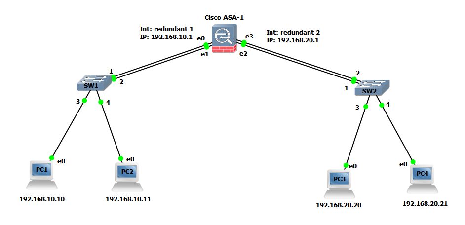 PC1 and PC2 are configured with 192.168.10.1 whereas PC3 and PC4 are configured with 192.168.20.1 as their default gateway.
To configure Redundant interface, follow the steps below:
ciscoasa#config term
ciscoasa(config)# interface redundant 1
ciscoasa(config-if)# member-interface gigabitEthernet 0
INFO: security-level and IP address are cleared on GigabitEthernet0.
ciscoasa(config-if)# member-interface gigabitEthernet 1
INFO: security-level and IP address are cleared on GigabitEthernet1.
ciscoasa(config-if)#
ciscoasa(config-if)# interface redundant 2
ciscoasa(config-if)# member-interface gigabitEthernet 2
ERROR: member interface must not have nameif configure.
ciscoasa(config-if)# member-interface gigabitEthernet 3
INFO: security-level and IP address are cleared on GigabitEthernet3.
ciscoasa(config)# interface gigabitEthernet 2
ciscoasa(config-if)# no nameif
ciscoasa(config-if)# no ip address
ciscoasa(config-if)# interface redundant 2
ciscoasa(config-if)# member-interface gigabitEthernet 2
INFO: security-level and IP address are cleared on GigabitEthernet2.
ciscoasa(config-if)#
In above configuration steps, the interface redundant command creates a logical redundant interface and then the member-interface command adds the physical gigabitEthernet interfaces on ASA as the members of logical redundant interface. The ASA will use both physical interfaces as a single virtual interface out of which one remains active (forwards traffic) and other remains standby. As soon as the active interface goes down, the standby member comes up and start passing the traffic.
Notice that the line marked Red in above configuration output shows Error while I tried to add a member interface gigabitEthernet 2. This is because the physical interface had nameif and IP address configured. You can not add a member interface until nameif, security-level and IP address are cleared from physical interface. When I cleared nameif and IP address from interface, it is successfully added as member interface of redundant 2.
Now that redundant 1 and redundant 2 interfaces are created, we have to issue no shutdown command for each physical interface to make sure every physical interface is enabled and then I will configure IP address and nameif on logical interfaces instead of physical.
ciscoasa(config)# interface gigabitEthernet 0
ciscoasa(config-if)# no shut
ciscoasa(config-if)# interface gigabitEthernet 1
ciscoasa(config-if)# no shut
ciscoasa(config-if)# interface gigabitEthernet 2
ciscoasa(config-if)# no shut
ciscoasa(config-if)# interface gigabitEthernet 3
ciscoasa(config-if)# no shut
ciscoasa(config)# interface redundant 1
ciscoasa(config-if)# nameif inside
INFO: Security level for "inside" set to 100 by default.
ciscoasa(config-if)# ip address 192.168.10.1 255.255.255.0
ciscoasa(config-if)# interface redundant 2
ciscoasa(config-if)# nameif outside
INFO: Security level for "outside" set to 0 by default.
ciscoasa(config-if)# ip address 192.168.20.1 255.255.255.0
ciscoasa(config-if)#
Now, you can use show interface redundant 1 and show interface redundant 2 command to verify the status of redundant interfaces.
ciscoasa# show interface redundant 1
Interface Redundant1 "inside", is up, line protocol is up
  Hardware is Linux Ethernet Dev, BW 100 Mbps, DLY 100 usec
        (Full-duplex), (100 Mbps)
        Input flow control is unsupported, output flow control is unsupported
        MAC address 0000.ab7c.9f00, MTU 1500
        IP address 192.168.10.1, subnet mask 255.255.255.0
        25 packets input, 2276 bytes, 0 no buffer
        Received 0 broadcasts, 0 runts, 0 giants
        0 input errors, 0 CRC, 0 frame, 0 overrun, 0 ignored, 0 abort
        0 pause input, 0 resume input
        3 L2 decode drops
        8 packets output, 616 bytes, 0 underruns
        0 pause output, 0 resume output
        0 output errors, 0 collisions, 0 interface resets
        0 late collisions, 0 deferred
        0 input reset drops, 0 output reset drops
        input queue (blocks free curr/low): hardware (0/0)
        output queue (blocks free curr/low): hardware (0/0)
  Traffic Statistics for "inside":
        22 packets input, 1780 bytes
        8 packets output, 504 bytes
        0 packets dropped
      1 minute input rate 0 pkts/sec,  14 bytes/sec
      1 minute output rate 0 pkts/sec,  0 bytes/sec
      1 minute drop rate, 0 pkts/sec
      5 minute input rate 0 pkts/sec,  1 bytes/sec
      5 minute output rate 0 pkts/sec,  0 bytes/sec
      5 minute drop rate, 0 pkts/sec
  Redundancy Information:
        Member GigabitEthernet0(Active), GigabitEthernet1
        Last switchover at 08:49:46 UTC Jul 30 2015
You can see under redundancy information that the Active interface is GigabitEthernet0 and GigabitEthernet1 is Standby.
You can also use below command to only list member interfaces:
ciscoasa# show interface redundant 1 | grep Member
        Member GigabitEthernet0(Active), GigabitEthernet1
ciscoasa#
After this configuration, PC1 and PC2 should be able to ping their gateway address (192.168.10.1). Similarly PC3 and PC4 should be able to ping their gateway (192.168.20.1)
PC1> ping 192.168.10.1
84 bytes from 192.168.10.1 icmp_seq=1 ttl=255 time=2.294 ms
84 bytes from 192.168.10.1 icmp_seq=2 ttl=255 time=5.621 ms
84 bytes from 192.168.10.1 icmp_seq=3 ttl=255 time=2.078 ms
84 bytes from 192.168.10.1 icmp_seq=4 ttl=255 time=3.301 ms
84 bytes from 192.168.10.1 icmp_seq=5 ttl=255 time=1.846 ms

PC1> show arp

00:00:ab:7c:9f:00  192.168.10.1 expires in 106 seconds
Note the MAC address resolved by PC1 for 192.168.10.1 is 00:00:ab:7c:9f:00. Now I will go to ASA and determine which interface this MAC address belong to?
ciscoasa# show interface | include (Interface|MAC)
Interface GigabitEthernet0 "", is up, line protocol is up
        MAC address 0000.ab7c.9f00, MTU not set
Interface GigabitEthernet1 "", is up, line protocol is up
        MAC address 0000.ab7c.9f01, MTU not set
Interface GigabitEthernet2 "", is up, line protocol is up
        MAC address 0000.ab7c.9f02, MTU not set
Interface GigabitEthernet3 "", is up, line protocol is up
You can see from above output that MAC address 00:00:ab:7c:9f:00 belongs to Interface gigabitEthernet0 since this is working as Active member for logical interface redundant 1. As soon as the Active interface goes down, the interface GigabitEthernet 1 will start forwarding traffic and this changeover process happens so quickly that the PC1 and PC2 will not notice anything.
To manually change the Active interface on ASA, you can enter the following command:
ciscoasa# redundant-interface Redundant 1 active-member gigabitEthernet 1
Configuring an EtherChannel
EtherChannel is a technology that allows you to aggregate multiple physical links of the same capabilities into a single logical one. In this way you can increase the bandwidth of a particular connection mitigating bottlenecks. You can configure up to 48 EtherChannels in Cisco ASA and each channel group can have eight active interfaces. However, you can assign up to 16 interfaces to a channel group, only eight interfaces can be active and the remaining interfaces can act as standby links in case of interface failure. By default, port-channel interfaces are enabled.
In this section, we will discuss how to create an EtherChannel port-channel interface, assign interfaces to the EtherChannel, and customize the EtherChannel.
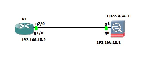 According to diagram shown above, I am going to bundle the links between R1 and ASA-1.
ciscoasa#config t
ciscoasa(config)# int gigabitEthernet0
ciscoasa(config-if)# channel-group 1 mode active
INFO: security-level and IP address are cleared on GigabitEthernet0.
ciscoasa(config-if)# lacp port-priority ?

interface mode commands/options:
  <1-65535>  Priority value
ciscoasa(config-if)# lacp port-priority 8000
ciscoasa(config)# interface gigabiEthernet1
ciscoasa(config-if)# channel-group 1 mode active
INFO: security-level and IP address are cleared on GigabitEthernet1.
ciscoasa(config-if)# lacp port-priority 9000
ciscoasa(config-if)#
ciscoasa(config-if)# interface port-channel 1
ciscoasa(config-if)# lacp max-bundle 4
ciscoasa(config-if)# port-channel min-bundle 2
ciscoasa(config-if)# port-channel load-balance src-dst-mac
ciscoasa(config-if)# lacp system-priority 10000
ciscoasa(config-if)# nameif inside
INFO: Security level for "inside" set to 100 by default.
ciscoasa(config-if)# ip address 192.168.10.1 255.255.255.0
Let us discuss each command in details now:
The first step is to select the physical interface and then channel-group channel_id mode {active | passive | on} command is used to create EtherChannel. The channel_id can be any number between 1 -48 and the mode can be active, passive or on.
ASA uses Link Aggregation Control Protocol (LACP) which aggregates interfaces by exchanging the Link Aggregation Control Protocol Data Units (LACPDUs) between two devices.
You can configure each physical interface in an EtherChannel to be:
• Active — Sends and receives LACP updates. An active EtherChannel can establish connectivity with either an active or a passive EtherChannel. You should use the active mode unless you need to minimize the amount of LACP traffic.
• Passive — Receives LACP updates. A passive EtherChannel can only establish connectivity with an active EtherChannel.
• On — The EtherChannel is always on, and LACP is not used. The “on” EtherChannel can only establish a connection with another “on” EtherChannel.
The lacp port-priority command sets the priority for a physical interface in the channel group between 1 and 65535. The default is 32768. The higher the number, the lower the priority. The ASA uses this setting to decide which interfaces are active and which are standby if you assign more interfaces than can be used. If the port priority setting is the
same for all interfaces, then the priority is determined by the interface ID (slot/port). The lowest interface ID is the highest priority. For example, GigabitEthernet 0 is a higher priority than GigabitEthernet 1.
If you want to prioritize an interface to be active even though it has a higher interface ID, then set this command to have a lower value. For example, to make GigabitEthernet 1 active before GigabitEthernet 0, then make the lacp port-priority value be lower than default value of 32768.
Then, I have selected the EtherChannel 1 interface using interface port-channel 1 command and then run some customization commands.
The lacp max-bundle command specifies the maximum number of active interfaces allowed in the channel group, between 1 and 8. The default is 8.
The port-channel min-bundle command specifies the minimum number of active interfaces required for the port-channel interface to become active, between 1 and 8. The default is 1. If the active interfaces in the channel group falls below this value, then the port-channel interface goes down, and could trigger a device-level failover.
The port-channel load-balance command configures the load-balancing algorithm. By default, the ASA balances the packet load on interfaces according to the source and destination IP address (src-dst-ip) of the packet. If you want to change the properties on which the packet is categorized, use this command. For example, if your traffic is biased heavily towards the same source and destination IP addresses, then the traffic assignment to interfaces in the EtherChannel will be unbalanced. Changing to a different algorithm can result in more evenly distributed traffic.
The lacp system-priority command sets the LACP system priority, from 1 to 65535. The default is 32768. The higher the number, the lower the priority. This command is global for the ASA. If the device at the other end of the EtherChannel has conflicting port priorities, the system priority is used to determine which port priorities to use.
Finally, I assigned name and IP address to EtherChannel interface.
You can use show port-channel and show interface port-channel commands to view EtherChannel statistics.
ciscoasa# show port-channel 1
Ports: 2   Maxports = 16
Port-channels: 1 Max Port-channels = 48
Protocol: LACP/ active
Minimum Links: 2
Maximum Bundle: 4
Load balance: src-dst-mac
Configuring VLAN Subinterfaces and 802.1Q Trunking
Subinterfaces let you divide a physical, redundant, or EtherChannel interface into multiple logical interfaces that are tagged with different VLAN IDs. An interface with one or more VLAN subinterfaces is automatically configured as an 802.1Q trunk. Because VLANs allow you to keep traffic separate on a given physical interface, you can increase the number of interfaces available to your network without adding additional physical interfaces in ASAs. This feature is particularly useful in multiple context mode so that you can assign unique interfaces to each context.
Step 1 Use the command interface {physical_interface | redundant number | port-channel number}.subinterface, where redundant number is the redundant interface ID, such as redundant 1. The port-channel number is the EtherChannel interface ID, such as port-channel 1. The subinterface ID is an integer between 1 and 4294967293.
Example:
ciscoasa(config)# interface gigabitEthernet 3.100
ciscoasa(config-subif)#
Step 2 Specify the VLAN for the subinterface using vlan vlan_id, where vlan_id is an integer between 1 and 4094. Some VLAN IDs might be reserved on connected switches, so check the switch documentation for more information. You can only assign a single VLAN to a subinterface, and you cannot assign the same VLAN to multiple subinterfaces. You cannot assign a VLAN to the physical interface. Each subinterface must have a VLAN ID before it can pass traffic.
Example:
ciscoasa(config-subif)# vlan 102
Monitoring Interfaces in Cisco ASA
To monitor interfaces, enter one of the following commands:
- show interface : Displays interface statistics.
- show interface ip brief : Displays interface IP addresses and status.
- show lacp {[channel_group_number] {counters | internal | neighbor} | sys-id} : Displays LACP information such as traffic statistics, system identifier and neighbor details for EtherChannel.
- show port-channel [channel_group_number] [brief | detail | port | protocol | summary] : Displays EtherChannel information in a detailed and one-line summary form. This command also displays the port and port-channel information.
- show port-channel channel_group_number load-balance [hash-result {ip | ipv6 | l4port | mac | mixed | vlan-only} parameters] : Displays port-channel load-balance information along with the hash result and member interface selected for a given set of parameters for EtherChannel.
This completes the Interface Configuration when you are using ASA in Routed Mode.
In the next section, we will discuss about Interface Configuration in Transparent Mode.