
- July 8, 2015
- Posted by: Surender Kumar
- Category: Cisco Switches
Cisco Catalyst Switch Configuration
Table of Contents
Cisco Catalyst switches come in many flavors. Some of them run 100Mbps FastEthernet switched ports like 2960 series, and some of them runs up to 10Gbps switched ports with a combination of twisted-pair and fiber. These newer switches (specially 3850 series) give you Unified Access. Cisco Unified Access is the convergence of the wired and wireless networks into one physical infrastructure by supporting wireless tunnel termination and full wireless LAN controller functionality. These switches offer greater intelligence, simplicity, performance, and open interfaces.
Catalyst series switches come in both Layer-2 and Layer-3 variants. Firstly, we will look into how to start up and configure a Cisco catalyst switch using command-line interface. After basic configuration, I will show you how to configure Virtual LANs (VLANs), inter-VLAN routing and VTP (Vlan Trunking Protocol).
In this section, we will cover the following:
- Administrative functions
- Configuring the IP address and subnet mask
- Setting up port security
- Setting up PortFast
- Enabling BPDUGuard and BPDUFilter
- Enabling UplinkFast
- Enabling BackboneFast
- Enabling RSTP (802.1w)
- Configuring EtherChannel
- Configure STP Root Bridge
Catalyst Switch Configuration Guide
I will use following network diagram to demonstrate catalyst switch configuration.
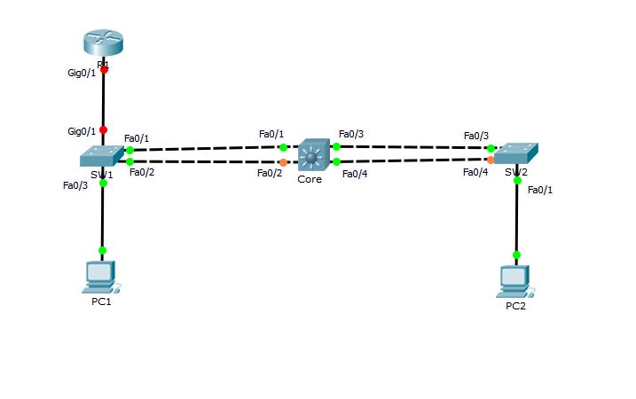
Before getting started to configuration, I would like to tell you that in above topology, Switches SW1 and SW2 are Cisco catalyst 2960 (layer-2), Core switch is Cisco catalyst 3550 (layer-3) and the Router R1 is Cisco 1841. PC1 and PC2 are Windows hosts.
Basic configuration of Cisco switches and bootup process is approximately same to that of Cisco routers which we have already discussed in Routers section. If you are new to this website, I would recommend you to read the getting started guide here and read basic IOS management steps here.
Administrative Functions
Okay, Now let’s start setting up basic administrative functions by connecting to each device one by one.
SW1 Configuration
Switch>en
Switch#conf t
Enter configuration commands, one per line.  End with CNTL/Z.
Switch(config)#hostname SW1
SW1(config)#enable secret cisco
SW1(config)#no ip domain-lookup
SW1(config)#int fa0/1
SW1(config-if)#description 1st connection to Core switch
SW1(config-if)#int fa0/2
SW1(config-if)#description 2nd connection to Core switch
SW1(config-if)#int fa0/3
SW1(config-if)#description Connection to PC1
SW1(config-if)#int Gig0/1
SW1(config-if)#description Connection to R1
SW1(config-if)#exit
SW1(config)#line vty 0 ?
  <1-15>  Last Line number
  <cr>
SW1(config)#line vty 0 15
SW1(config-line)#password cisco@123
SW1(config-line)#login
SW1(config-line)#exit
SW1(config)#int vlan 1
SW1(config-if)#ip address 192.168.1.10 255.255.255.0
SW1(config-if)#no shut
SW1(config-if)#exit
%LINK-5-CHANGED: Interface Vlan1, changed state to up

%LINEPROTO-5-UPDOWN: Line protocol on Interface Vlan1, changed state to up

SW1(config)#banner motd ### WELCOME TO SW1 ###
SW1(config)#end
SW1#
%SYS-5-CONFIG_I: Configured from console by console

SW1#copy running-config startup-config
Destination filename [startup-config]?
Building configuration...
[OK]
SW1#
The above configuration steps are pretty straightforward if you have read Cisco Router Configuration Guide in Routers section. All the ports on Cisco switches are enabled by default (unlike Cisco routers). So, you need not to issue no shutdown command for any interface. For layer-2 switching, we do not need to configure any IP address on switch ports and no routing protocols are required. The IP address is only needed under management interface which is VLAN 1 for accessing the Switch through network. Since VLAN interface is by default disabled. So, I have used no shut command to enable it. And finally, I saved the switch configuration using copy run start command.
SW2 Configuration
Switch>en
Switch#config t
Enter configuration commands, one per line.  End with CNTL/Z.
Switch(config)#enable secret cisco
Switch(config)#no ip domain-lookup
Switch(config)#int fa0/3
Switch(config-if)#description 1st connection to Core switch
Switch(config-if)#int fa0/4
Switch(config-if)#description 2nd connection to Core switch
Switch(config-if)#int fa0/1
Switch(config-if)#description Connection to PC2
Switch(config-if)#line vty 0 15
Switch(config-line)#password cisco@123
Switch(config-line)#login
Switch(config-line)#int vlan 1
Switch(config-if)#ip address 192.168.1.11 255.255.255.0
Switch(config-if)#no shutdown
Switch(config-if)#
%LINK-5-CHANGED: Interface Vlan1, changed state to up

%LINEPROTO-5-UPDOWN: Line protocol on Interface Vlan1, changed state to up

Switch(config-if)#exit
Switch(config)#banner motd ### WELCOME to SW2 ###
Switch(config)#hostname SW2
SW2(config)#end
SW2#
%SYS-5-CONFIG_I: Configured from console by console

SW2#write
Building configuration...
[OK]
SW2#
Similarly, Switch SW2 is also configured. Since both SW1 and SW2 are assigned IP address of same subnet and both are connected to each other. We should now be able to ping SW1 from SW2.
SW2#ping 192.168.1.10

Type escape sequence to abort.
Sending 5, 100-byte ICMP Echos to 192.168.1.10, timeout is 2 seconds:
!!!!!
Success rate is 100 percent (5/5), round-trip min/avg/max = 0/3/10 ms

SW2#
You can see that we can ping SW1 from SW2.
Core Configuration
Switch>en
Switch#conf t
Enter configuration commands, one per line.  End with CNTL/Z.
Switch(config)#hostname Core
Core(config)#enable secret cisco
COre(config)#no ip domain-lookup
Core(config)#int fa0/1
Core(config-if)#description 1st connection to SW1
Core(config-if)#int fa0/2
Core(config-if)#description 2nd connection to SW1
Core(config-if)#int fa0/3
Core(config-if)#description 1st connection to SW2
Core(config-if)#int fa0/4
Core(config-if)#description 2nd connection to SW2
Core(config-if)#line vty 0 15
Core(config-line)#password cisco@123
Core(config-line)#login
Core(config-line)#int vlan 1
Core(config-if)#ip address 192.168.1.12 255.255.255.0
Core(config-if)#no shutdown
Core(config-if)#
%LINK-5-CHANGED: Interface Vlan1, changed state to up

%LINEPROTO-5-UPDOWN: Line protocol on Interface Vlan1, changed state to up

Core(config-if)#exit
Core(config)#banner motd ### WELCOME TO CORE SWITCH ###
Core(config)#end
Core#
%SYS-5-CONFIG_I: Configured from console by console

Core#copy run start
Destination filename [startup-config]?
Building configuration...
[OK]
Core#
There is nothing different in Core switch configuration.
Let’s ping SW1 and SW2 from Core switch to confirm that all switches can communicate among each other. Before running ping, you can verify the ARP cache on Core switch by using show arp command.
Core#show arp
Protocol  Address          Age (min)  Hardware Addr   Type   Interface
Internet  192.168.1.12            -   0090.21AA.68CB  ARPA   Vlan1
Core#
You can see that ARP cache only has MAC address of Vlan1 interface.
Core#ping 192.168.1.10

Type escape sequence to abort.
Sending 5, 100-byte ICMP Echos to 192.168.1.10, timeout is 2 seconds:
.!!!!
Success rate is 80 percent (4/5), round-trip min/avg/max = 0/0/0 ms

Core#ping 192.168.1.11

Type escape sequence to abort.
Sending 5, 100-byte ICMP Echos to 192.168.1.11, timeout is 2 seconds:
.!!!!
Success rate is 80 percent (4/5), round-trip min/avg/max = 0/0/0 ms

Core#
Did you notice each ping response? Why did only 4 ping packets got successive reply out 5 packets?
This is due to Address Resolution Protocol (ARP) timeout. At first ping, Core switch was not aware of MAC address of SW1 and SW1. So, it made an ARP broadcast saying who has IP address of 192.168.1.10? Since SW1 has IP address 192.168.1.10 configured on vlan1 interface, it replied to Core Switch with its MAC address and the MAC address is now cached by Core switch. Same process happens for SW2. Address Resolution Protocol (ARP) works in this way. You can again check ARP cache on Core switch.
Core#show arp
Protocol  Address          Age (min)  Hardware Addr   Type   Interface
Internet  192.168.1.10            9   000D.BD47.AB46  ARPA   Vlan1
Internet  192.168.1.11            9   00D0.BC48.ABA6  ARPA   Vlan1
Internet  192.168.1.12            -   0090.21AA.68CB  ARPA   Vlan1
Core#
Now that the Core switch know that MAC address of vlan1 on both SW1 and SW2, ping will not fail again due to ARP.
Core#ping 192.168.1.11

Type escape sequence to abort.
Sending 5, 100-byte ICMP Echos to 192.168.1.11, timeout is 2 seconds:
!!!!!
Success rate is 100 percent (5/5), round-trip min/avg/max = 0/0/1 ms

Core#
You can see this time Core switch got 100% success in ping.
Setting up Port Security
The switchport security is one of the most important feature offered by Cisco catalyst switches. It offers the ability to configure a switchport so that traffic can be limited to only a specific configured MAC address or list of MAC addresses.
To begin with, there are three different types of secure MAC address:
- Static secure MAC address — Static secure MAC addresses are typically used when the MAC addresses used are known and do not change often. For example, if a single host is always connected to the same switchport.
- Dynamic secure MAC address — Dynamic secure MAC addresses are typically used when the host(s) connecting to a specific switchport is constantly changing, and the intention is to limit the port to only be used by a specific number of hosts at once. For example, a switchport can be configured to only allow a single MAC address to be learned at a time and not permit hosts other than the one initially learned.
- Sticky secure MAC address — Sticky secure MAC addresses are a bit of a combination between the two prior secure MAC address types; not only are addresses able to be statically-configured but they can also be dynamically learned. The key difference here is that dynamically-learned addresses are automatically put into the running-configuration; if the engineer wants these addresses to be saved on device reboot, the option is available to save the running-configuration into the startup configuration, thus effectively making these addresses static.
The type of secure MAC address that is configured depends on the intended end result.
Switchport Security Violations
The other option in switchport port-security that must be used is a security violation mode which tells the switch what action should be taken when any security violation occurs. A switchport violation occurs in one of two situations:
- When the maximum number of secure MAC addresses has been reached (by default, the maximum number of secure MAC addresses per switchport is limited to 1)
- An address learned or configured on one secure interface is seen on another secure interface in the same VLAN.
The action that the device takes when one of these violations occurs can be configured:
- Protect — This mode permits traffic from known MAC addresses to continue to be forwarded while dropping traffic from unknown MAC addresses when over the allowed MAC address limit. When configured with this mode, no notification action is taken when traffic is dropped.
- Restrict — This mode permits traffic from known MAC addresses to continue to be forwarded while dropping traffic from unknown MAC addresses when over the allowed MAC address limit. When configured with this mode, a syslog message is logged, a Simple Network Management Protocol (SNMP) trap is sent, and a violation counter is incremented when traffic is dropped.
- Shutdown — This mode is the default violation mode. In this mode, the switch will automatically force the switchport into an error disabled (err-disable) state when a violation occurs. While in this state, the switchport forwards no traffic. The switchport can be brought out of this error disabled state by issuing the errdisable recovery cause CLI command or by disabling and re-enabling the switchport.
In our sample network topology, the end hosts PC1 and PC2 are connected to SW1 and SW2 only, we will configure port security on specific ports so that only PC1 and PC2 can use these ports. If any other MAC address is detected by the switch, the port will automatically enter error disable state (shutdown).
On SW1:
SW1#conf t
Enter configuration commands, one per line.  End with CNTL/Z.
SW1(config)#int fa0/3
SW1(config-if)#switchport port-security mac-address ?
  H.H.H   48 bit mac address
  sticky  Configure dynamic secure addresses as sticky
SW1(config-if)#switchport port-security mac-address 000A.F3C5.2282
Port-security not enabled on interface FastEthernet0/3.
SW1(config-if)#switchport port-security maximum 1
SW1(config-if)#switchport port-security violation ?
  protect   Security violation protect mode
  restrict  Security violation restrict mode
  shutdown  Security violation shutdown mode
SW1(config-if)#switchport port-security violation shutdown
SW1(config-if)#switchport port-security
Command rejected: FastEthernet0/3 is a dynamic port.
SW1(config-if)#switchport mode access
SW1(config-if)#switchport port-security
SW1(config-if)#end
SW1#
In above configuration, I would like to point out some important things.
I have selected the port FastEthernet0/3 and then used switchport port-security mac-address command followed by the MAC address of PC1 to configure secure MAC address on this port. I could also use sticky keyword instead of typing complete mac address. In large networks, it is not feasible for an administrator to manually type MAC addresses of all PCs. Did you notice the line marked red? This was due to fact that every switch port is by default in dynamic mode and the switch rejected the command. I configured the port to be an access (static) port and then the command was accepted.
Now, you can view the status of port security using show port security and show port-security interface commands.
SW1#show port-security
Secure Port MaxSecureAddr CurrentAddr SecurityViolation Security Action
               (Count)       (Count)        (Count)
--------------------------------------------------------------------
        Fa0/3        1          1                 0         Shutdown
----------------------------------------------------------------------
On SW2:
SW2#conf t
Enter configuration commands, one per line.  End with CNTL/Z.
SW2(config)#int fa0/1
SW2(config-if)#switchport mode access
SW2(config-if)#switchport port-security
SW2(config-if)#switchport port-security mac-address sticky
SW2(config-if)#switchport port-security maximum ?
  <1-132>  Maximum addresses
SW2(config-if)#switchport port-security maximum 1
SW2(config-if)#switchport port-security violation shutdown
SW2(config-if)#end
SW2#
Setting up PortFast
If we use the portfast command on our switches, it will not cause the DHCP request of our hosts to possibly timeout because Spanning Tree Protocol takes way too long to converge. So I am going to use PortFast on port fa0/3 and fa0/1 on both switches SW1 and SW2 respectively.
SW1(config)#int fa0/3
SW1(config-if)#spanning-tree portfast
%Warning: portfast should only be enabled on ports connected to a single host. Connecting hubs, concentrators, switches, bridges, etc... to this interface when portfast is enabled, can cause temporary bridging loops.
Use with CAUTION

%Portfast has been configured on FastEthernet0/3 but will only
have effect when the interface is in a non-trunking mode.
SW1(config-if)#end
SW1#
SW2(config)#int fa0/1
SW2(config-if)#spanning-tree portfast
%Warning: portfast should only be enabled on ports connected to a single host. Connecting hubs, concentrators, switches, bridges, etc... to this interface when portfast is enabled, can cause temporary bridging loops.
Use with CAUTION

%Portfast has been configured on FastEthernet0/1 but will only
have effect when the interface is in a non-trunking mode.
SW2(config-if)#end
SW2#
Using PortFast can be dangerous because it increases the possibility of creating switching loops in network. So, there are some safeguard commands you can use when using PortFast in case someone accidentally causes a loop in a port configured with PortFast. These safeguard commands are BPDUGuard and BPDUFilter.
Enabling BPDUGuard and BPDUFilter
BPDUGuard: If a switch port that has PortFast enabled receives a BPDU on that port, iswitch will place the port into error disabled state. This stops an administrator from accidentally connecting another switch or hub port into a switch port configured with PortFast. You should only configure this command on your Access layer where users are directly connected. So, we would not configure this on our Core switch.
BPDUFilter: Since a switch port that has PortFast enabled will still receive BPDUs by default, you can use BPDUFilter to completely stop BPDUs from coming to or going from that port. BPDUFilter filtering will immediately take a port out of PortFast if it receives a BPDU and force the port to be part of the STP topology again. Unlike BPDUGuard, which places the port into error disabled state, the BPDUFilter will keep a port up, but without PortFast running. There is just no reason to have BPDUs received on an interface configured with PortFast.
Now, let us configure our SW1 and SW2 interfaces that are already configured with PortFast.
SW1(config)#int fa0/3
SW1(config-if)#spanning-tree bpduguard enable
SW1(config-if)#spanning-tree bpdufilter enable
SW1(config-if)#
SW2(config)#int fa0/1
SW2(config-if)#spanning-tree bpduguard enable
SW2(config-if)#spanning-tree bpdufilter enable
SW2(config-if)#
Enabling UplinkFast
Lets now configure UplinkFast on SW1 and SW2.
SW1#conf t
Enter configuration commands, one per line.  End with CNTL/Z.
SW1(config)#spanning-tree uplinkfast
SW1(config)#end
SW2#conf t
Enter configuration commands, one per line.  End with CNTL/Z.
SW2(config)#spanning-tree uplinkfast
SW2(config)#end
SW2#
Note that uplinkfast command is a global config mode command and it is enabled on every port.
Enabling BackboneFast
BackboneFast is used to determine link failures on a remote switch unlike UplinkFast. So, I can enable this on every switch including Core.
SW1#config t
Enter configuration commands, one per line.  End with CNTL/Z.
SW1(config)#spanning-tree backbonefast
SW1(config)#
SW2#config t
Enter configuration commands, one per line.  End with CNTL/Z.
SW2(config)#spanning-tree backbonefast
SW2(config)#
You can use show spanning-tree backbonefast command to view the status.
Enabling Rapid Spanning Tree Protocol (802.1w)
802.1D Spanning Tree Protocol (STP) has a drawback of slow convergence. Cisco Catalyst switches support three types of STPs, which are PVST+, rapid-PVST+ and MST (multiple spanning tree). PVST+ is based on IEEE802.1D standard and includes Cisco proprietary extensions such as BackboneFast, UplinkFast and PortFast. Rapid-PVST+ is based on IEEE 802.1w standard and has a faster convergence than 802.1D. RSTP (IEEE 802.1w) natively includes most of the Cisco proprietary enhancements to the 802.1D Spanning Tree, such as BackboneFast and UplinkFast.
Configuring RSTP actually is very easy. Lets first enable it on Core switch.
Core#conf t
Enter configuration commands, one per line.  End with CNTL/Z.
Core(config)#spanning-tree mode ?
  pvst        Per-Vlan spanning tree mode
  rapid-pvst  Per-Vlan rapid spanning tree mode
Core(config)#spanning-tree mode rapid-pvst
Core(config)#
SW1(config)#spanning-tree mode rapid-pvst
SW1(config)#
SW2(config)#spanning-tree mode rapid-pvst
SW2(config)#end
You can see the status of RSTP using show spanning-tree command
Core#show spanning-tree
VLAN0001
  Spanning tree enabled protocol rstp
  Root ID    Priority    32769
             Address     000D.BD47.AB46
             Cost        19
             Port        1(FastEthernet0/1)
             Hello Time  2 sec  Max Age 20 sec  Forward Delay 15 sec

  Bridge ID  Priority    32769  (priority 32768 sys-id-ext 1)
             Address     0090.21AA.68CB
             Hello Time  2 sec  Max Age 20 sec  Forward Delay 15 sec
             Aging Time  20

Interface        Role Sts Cost      Prio.Nbr Type
---------------- ---- --- --------- -------- --------------------------------
Fa0/1            Root FWD 19        128.1    P2p
Fa0/2            Altn BLK 19        128.2    P2p
Fa0/3            Desg FWD 19        128.3    P2p
Fa0/4            Desg FWD 19        128.4    P2p

Core#
Configuring EtherChannel
I will bundle the links between the SW1 switch and the Core switch using interface port-channel global command and the channel-group and channel-protocol interface config commands on the SW1 and Core switches.
On SW1:
SW1#conf t
Enter configuration commands, one per line.  End with CNTL/Z.
SW1(config)#interface port-channel 1
SW1(config-if)#int range fa0/1-2
SW1(config-if-range)#switchport mode trunk
SW1(config-if-range)#
%LINEPROTO-5-UPDOWN: Line protocol on Interface FastEthernet0/1, changed state to down

%LINEPROTO-5-UPDOWN: Line protocol on Interface FastEthernet0/1, changed state to up

%LINEPROTO-5-UPDOWN: Line protocol on Interface FastEthernet0/2, changed state to down

%LINEPROTO-5-UPDOWN: Line protocol on Interface FastEthernet0/2, changed state to up

SW1(config-if-range)#switchport nonegotiate
SW1(config-if-range)#channel-group 1 mode auto
SW1(config-if-range)#
%LINEPROTO-5-UPDOWN: Line protocol on Interface FastEthernet0/1, changed state to down

%LINEPROTO-5-UPDOWN: Line protocol on Interface FastEthernet0/1, changed state to up

%LINEPROTO-5-UPDOWN: Line protocol on Interface FastEthernet0/2, changed state to down

%LINEPROTO-5-UPDOWN: Line protocol on Interface FastEthernet0/2, changed state to up

SW1(config-if-range)#end
SW1#
On Core:
Core#conf t
Enter configuration commands, one per line.  End with CNTL/Z.
Core(config)#int port-channel 1
Core(config-if)#int range fa0/1-2
Core(config-if-range)#switchport trunk encapsulation dot1q

%%EC-5-COMPATIBLE: Fa0/1  is compatible with port-channel members

%%EC-5-COMPATIBLE: Fa0/2  is compatible with port-channel members
Core(config-if-range)#switchport mode trunk
Core(config-if-range)#channel-group 1 mode desirable
Core(config-if-range)#switchport nonegotiate
Core(config-if-range)#do show int port-channel 1
Port-channel 1 is up, line protocol is up (connected)
  Hardware is EtherChannel, address is 0090.0cc6.b9c0 (bia 0090.0cc6.b9c0)
  MTU 1500 bytes, BW 300000 Kbit, DLY 1000 usec,
     reliability 255/255, txload 1/255, rxload 1/255
  Encapsulation ARPA, loopback not set
  Keepalive set (10 sec)
  Half-duplex, 300Mb/s
  input flow-control is off, output flow-control is off
  Members in this channel: Fa0/1 ,Fa0/2 ,
  ARP type: ARPA, ARP Timeout 04:00:00
  Last input 00:00:08, output 00:00:05, output hang never
  Last clearing of "show interface" counters never
  Input queue: 0/75/0/0 (size/max/drops/flushes); Total output drops: 0
  Queueing strategy: fifo
  Output queue :0/40 (size/max)
  5 minute input rate 0 bits/sec, 0 packets/sec
  5 minute output rate 0 bits/sec, 0 packets/sec
     956 packets input, 193351 bytes, 0 no buffer
     Received 956 broadcasts, 0 runts, 0 giants, 0 throttles
     0 input errors, 0 CRC, 0 frame, 0 overrun, 0 ignored, 0 abort
     0 watchdog, 0 multicast, 0 pause input
     0 input packets with dribble condition detected
     2357 packets output, 263570 bytes, 0 underruns
     0 output errors, 0 collisions, 10 interface resets
     0 babbles, 0 late collision, 0 deferred
     0 lost carrier, 0 no carrier
     0 output buffer failures, 0 output buffers swapped out
Core(config-if-range)#end
Configure STP Root Bridge
We have already discussed about the election of Root bridge in our previous section. By default, Root bridge is elected on the basis of Lowest Bridge ID. But when networks are designed in hierarchical fashion keeping the three layered network model into consideration, It is always a good idea to force the Core Switches to be Root of STP domain. You can do this in two ways. First way is that you can lower the Bridge Priority of Core Switch because Priority is used to determine Bridge ID. Second way is that you use spanning-tree vlan 1 root primary global command to force the desired switch to be Root of STP domain.
I am going to do this by lowering the priority of Core switch in our sample network.
You can see below that currently SW1 is the Root bridge in our network.
SW1#show spanning-tree
VLAN0001
  Spanning tree enabled protocol rstp
  Root ID    Priority    32769
             Address     000D.BD47.AB46
             This bridge is the root
             Hello Time  2 sec  Max Age 20 sec  Forward Delay 15 sec

  Bridge ID  Priority    32769  (priority 32768 sys-id-ext 1)
             Address     000D.BD47.AB46
             Hello Time  2 sec  Max Age 20 sec  Forward Delay 15 sec
             Aging Time  20

Interface        Role Sts Cost      Prio.Nbr Type
---------------- ---- --- --------- -------- --------------------------------
Fa0/3            Desg FWD 19        128.3    P2p
Po1              Desg FWD 9         128.27   Shr

SW1#
But we wanted our Core switch to be Root. You can verify the priority of SW1 and SW2 using show spanning tree command. Remember that the lowest priority is best. So, I will configure the priority of Core switch to something which is lowest from SW1 and SW2. Therefore, The Core will be elected as Root.
Core#conf t
Enter configuration commands, one per line.  End with CNTL/Z.
Core(config)#spanning-tree vlan 1 priority ?
  <0-61440>  bridge priority in increments of 4096
Core(config)#spanning-tree vlan 1 priority 10000
% Bridge Priority must be in increments of 4096.
% Allowed values are:
  0     4096  8192  12288 16384 20480 24576 28672
  32768 36864 40960 45056 49152 53248 57344 61440
Core(config)#spanning-tree vlan 1 priority 20480
Core(config)#end
Core#
%SYS-5-CONFIG_I: Configured from console by console

Core#
Core#show spanning-tree
VLAN0001
  Spanning tree enabled protocol rstp
  Root ID    Priority    20481
             Address     0090.21AA.68CB
             This bridge is the root
             Hello Time  2 sec  Max Age 20 sec  Forward Delay 15 sec

[output cut]
Immediately after lowering the priority value of Core switch, network will start converging again and once converged, you will see Core switch is now acting as Root bridge.
Verify the Switch Configuration
Now, we need to verify our switch configurations. The best command to start is show running-config because this command will show a complete configuration of every device. Then you can use show ip interface brief command to list the status of interfaces. The status of Line and Protocol for interfaces which are connected should be up and up. See the output of command on Core switch.
Core#show ip interface brief
Interface              IP-Address      OK? Method Status                Protocol

FastEthernet0/1        unassigned      YES unset  up                    up

FastEthernet0/2        unassigned      YES unset  up                    up

FastEthernet0/3        unassigned      YES unset  up                    up

FastEthernet0/4        unassigned      YES unset  up                    up

[output cut]

GigabitEthernet0/1     unassigned      YES unset  down                  down

GigabitEthernet0/2     unassigned      YES unset  down                  down

Vlan1                  192.168.1.12    YES manual up                    up

Port-channel 1         unassigned      YES unset  up                    up
Core#
You can also use show mac address-table command as shown below
SW1#show mac address-table
          Mac Address Table
-------------------------------------------

Vlan    Mac Address       Type        Ports
----    -----------       --------    -----

   1    0001.637c.b001    DYNAMIC     Fa0/1
   1    0001.637c.b002    DYNAMIC     Fa0/2
   1    000a.f3c5.2282    STATIC      Fa0/3
   1    0090.0cc6.b9c0    DYNAMIC     Po1
SW1#
In the next section we will discuss about Virtual LANs.